Para traducir a español usa el traductor que está en el panel de la derecha --->;
The Inspiration
The birth of Señor Plow idea takes place some years ago, when i was just at the beginning of my career. By that time, the robotics team (Semillero A+D) of my college (UPB Medellín) was a big one, we were young and full of ideas, willing to change the world with the power of engineering =D.
Objective: Develop a good Sumo robot that complies with the local Sumo competition rules.
Motivation: The satisfaction of creating something from nothing, our own robot, and that our robot could beat the hell out of other robots and win!
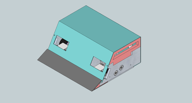
Result: Don Barredora, our team´s second Sumo robot.
 |
| Left: Don Barredora´s CAD design. Right: Don Barredora |
The name Don Barredora is the spanish translation for Mr. Plow, a character that Homer Simpson embodies on the fourth season of the series. I think a video will explain things better than i could do:
When we came up with the first design of Don Barredora, it had an obvious resemblance with Mr. Plow, added to the love of the team for The Simpsons, gave birth to the name of our robot.
Don Barredora was a success in various competitions, and we got some recognition from our college directives, it payed itself with the competition money prizes, but the biggest prize was to be recognized and to have gained support from our university for future events. In summary, this robot is in part responsible for our participation on international competitions, and it´s an inspiration for Señor Plow project.
 |
| PsychoBot (Left) Vs. Sora (Right) - PsychoBot flies 2 meters off the Dohyo |
The defeat wasn´t anything but a motivation to build a stronger, fastest, and overall better robot, so immediately after coming back to Colombia we started to build Señor Plow, the rebirth of Don Barredora!
Concept and Design of Señor Plow
Señor Plow´s design it´s based, in many aspects, on Vitalij Rodnov´s educational document about his Japanese-Style Sumo Robot Parazit, the document is available at the Baltic Robot Sumo website... Thank you Vitalij for sharing all that valuable information!
As i mentioned earlier, my design is also based on the experience acquired in the Japan Tournament, specially form Lucas Tetsuya, who took second place in Radio-Controlled category with his robot L, and Yasumichi Kijima, who took first place in Autonomous category with his robot Six Dimensional K. Thank you very much for your help guys!
The first step:
I defined a list of crucial characteristics that a Japanese-style robot sumo must have:
- Movement Speed: 4-5 meters/second
- Strength: motors that can move the robot taking into account a huge down-force caused by powerful magnets.
- Response Speed: Very fast sensors, very likely to be industrial type.
- Strategy development: A lot of sensors to have as much information about the surroundings of the robot as possible, and a CPU capable of processing all the information and strategies.
- Structure: Solid metal structure that withstand use and abuse, hits and falls.
- Rules: Have to comply with international rules, specially in japan, obviously!
Based on that list, i made the selection of some components, including the design of the gears.
Motors
It has been said by many japanese-style sumo robot builders, the best motors you can get for a DC brushed one of a size and weight that doesn't violate the rules are MAXON motors. they are REALLY expensive, but they worth it.
 |
| CAD model of the motors i use |
 |
| Specs of the Maxon 273753 and 273752, taken from maxon motor ag. |
The Maxon 27375x motors are just perfect, they have an efficiency of 84% and an extremely high torque at high speed. The question is... which is the best?
The 273752 has a lower nominal voltage, which means that you could apply an overvoltage easily and increase speed and torque. The 273753 has twice the nominal voltage of the 273752, which means that running it on overvoltage isn't that easy, but the peak current you have to handle is cut to half. Also, you can see that the specs of the 53 are slightly better.
I ran some simulations of the limit operative conditions of the motor. The parameters of the motor were taken from its datasheet, and a supply voltage of 50V (over-voltage) and a mechanical load of 2 N-m was used as conditions for the simulation.
 |
| Maxon 273753 model (mathworks Simulink). |
 |
| Results of the simulation |
As you can see, a torque of 2N-m could be delivered without exceeding nominal current values and obtaining a decent speed. Anyway, this is just a simulation, and i am ignoring a lot of details, probably in reality, things are not gonna be as pretty as they are here... and that, my friend, is the cruel real world =(
At the end, i went for the 273753. I am willing to take a risk and try to operate both motors over nominal voltage... i hope i'll survive =S.
The downside of this motor is it's price. the retailer's price is 300 Swiss francs (CHF), and multiply that for 2, 600 CHF ~= 604 dollars. PLUS importation taxes and shipping fees... to Colombia! that's a lot of money for an engineering student =S.
Anyway, i asked to Maxon sales representative to give me a student discount, and thankfully they discounted me 40% on the retailer's price. still... that's a lot of money.
Mechanical Design Version 1
having selected the motors for my robot, the next thing i thought was the mechanical design, which its first version is based on Mr. Kijima´s design. below are posted the pictures of what i did, explanation goes after the pictures:
Concept
The main concept of the design is equilibrium. The key to build a good robot is not just strength, speed or intelligence, but balance among these qualities. When i was choosing the distribution of mechanical parts, i found a wide variety of possibilities, but i preferred to stay with Mr. Kijima's approach. The motors are placed in the center of the robot. This choice carried a problem, the motor´s axis are not aligned, and thus, making the speed reducer a little bit more difficult to design.
Speed Reducer
Japanese sumo robots usually use gears for reducing the high speed output of the motors and convert it into torque. In the chart below you can see the calculations made for the speed reducer of this robot:
As you can see, this is a two-stage speed reducer, with a ratio of 1:5.14. with this motor's nominal speed, an output speed of the reducer would be around 1200 RPM, but i'm planning to increase motor's voltage over nominal, that should give some more RPMs. theoretically, you could achieve a speed of 2.65 m/s with this configuration, but, i will know when i test it.
Prototype 1
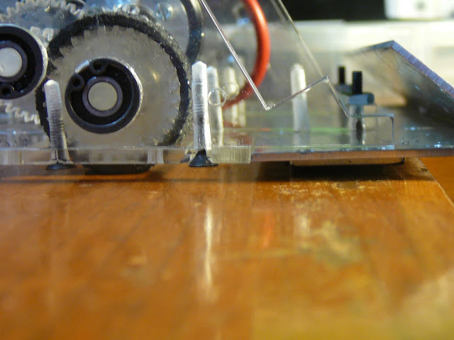
For evaluation purposes, an acrylic model of the robot was built. Specifically, i needed to check if the design of the gears was ok, and if the distribution of the parts was balanced and well made (besides, this model was a final project for mechatronics subject at my school).
Actually this model was not intended to move on combat conditions, mainly because the materials were frail and the motor drivers were not adequate for this motors.
Nonetheless, this model was built, and it proved that the placing of the gears, and the design in general was ok, but that needed some improvements.
If you want to read more details about this prototype, download the article clicking the link below. ---------------------------------------------------------------------------------------------------


Muy interesante, gracias por compartir toda esta información =)
ReplyDeleteGracias!
DeleteThanks dude, really helpfull, sorry I cannot help you with this one, but.. from Germany, kinda difficult :/ I do my best from here.
ReplyDeleteEh que bien hermano, esta muy interesante la información!
ReplyDelete¡Muchas gracias! subscríbete al blog para estar al tanto de actualizaciones que iré haciendo (en el panel de la derecha está la opción de subscripción por email)
DeleteHola Luis, muy buen proyecto, te felicito y gracias por hacer participe a la familia Colcircuitos de esta información. Como lo hemos hablado, si queremos apoyarte con la fabricación de la(s) PCB(s), ensamble e importación de partes.
ReplyDeleteQuedamos a tu disposición.
Gabriel Vélez.
Muchas gracias Gabriel, y gracias también a toda la gente de Colcircuitos, de verdad que aprecio mucho el apoyo. Estamos hablando pues.
Deletehello very interest news. I want buy the Motor, Wheel, etc pls contact me
ReplyDeleteThis comment has been removed by the author.
Deleteno vendes el diseño?????????????? para mandar cortar las piezas
ReplyDelete